It is well known that Mie 's scattering theory is mainly used for sub-micron to micron size segments. Light scattering below micron to nanometer is similar to the more explicit and simple Rayleigh scattering law, and similar to large particles larger than micrometer to millimeter. For the meaning of the Fraunhofer diffraction law. Using these laws, we can successfully explain various scattering phenomena and guide the particle size distribution of the particle . The Mie scattering theory is a Maxwell equation for the uniform uniformity of a single dielectric sphere in a uniform medium under monochromatic parallel illumination. A rigorous mathematical solution to the boundary conditions, which is currently the mainstream theory in particle testing.
Here we analyze the design of domestic and foreign particle scattering theory and testing technology based on a set of experiments using photonic technology to measure sub-micron particle scattering system information to carry out more in-depth study of Mie's scattering theory. In order to measure the particle size of the particles in the submicron or even nanometer range more accurately, the photon technology is used in the experiment to reasonably design the angle between the sample cell and the incident light, which improves the experimental precision and obtains the Mie theory. A good result is obtained , and a particle size analyzer using a fiber optic probe combined with a photomultiplier tube and a photon counter as a detector is proposed , which is better suited to the particle size test of submicron particles than a finite ring target , and can better interface with a computer. , to improve the test level, thereby greatly improving the resolution of small particle size measurement , and based on this, probed into a new generation of sub-micron particle detection instruments.
The study uses high-temporal resolution observation techniques, with physical simulation combined with experimental measurements as the main research tool. The He-Ne laser source is used to illuminate the uniformly dispersed particles, the scattering signal is received by the optical fiber, the scattering signal is amplified by the photomultiplier tube, and the scattering information of each particle under the action of the laser is measured by a photon counter. The quantitative result of the physical parameters of the particles in the measured field can be obtained by analyzing and calculating the scattered signal.
The schematic diagram of the optical path used in this experiment is as follows:
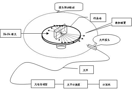
Figure 1 Â Mie scattering experiment light path diagram
Shown in Figure 1, a Mie's scattering experiments, the most important question is how the particles scatter light signal more precise detection, the main issues surrounding this experiment we will conduct a more thorough optical path design, which mainly In this experiment, the photon technology was introduced, and the optical fiber was used to collect the scattered signal. The signal was amplified by the photomultiplier tube and characterized by a photon counter. In this way, we can detect extremely weak scattered light and greatly improve the detection accuracy. In order to prevent the occurrence of stray light, we placed the laser outside the entire scattering system, allowing only the laser to enter the scattering system through a small hole, which also provided a strong guarantee for detecting accurate scattered signals.
Determination of the angle between the incident light and the sample cell
Why do you want to determine the angle between the sample cell and the incident light? Explain here. First, let's look at the incident when the light is perpendicular to the sample cell. As shown in Figure 2 , n 0 =1 , n 1 = 1.33 , n 2 = 1.5
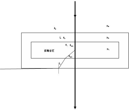
Figure 2 Â Vertical incidence diagram
When the incident light is incident perpendicularly on the sample cell, according to the law of refraction
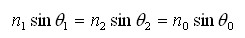
Where θ 1 is the angle of incidence of the scattered light outside the transparent wall of the sample cell, θ 2 is the angle of refraction of the scattered light in the transparent wall of the sample cell , and θ 0 is the angle of refraction of the scattered light outside the transparent wall of the sample cell. The scattering angle referred to here refers to the angle between the incident light and the scattered light in the scattering medium in the clockwise direction. For the sake of convenience, we can discuss the acute angle between the incident light and the incident light. :
( 1 ) due to 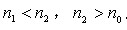
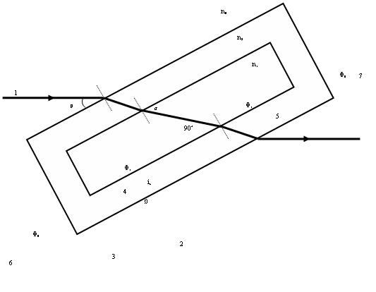
Figure 3 Â Schematic diagram of the angle between the incident light and the sample cell
As shown in Figure 3 , we let the incident light enter the sample cell at an angle θ . The incident light is refracted into the scattering medium twice, with the incident light in the scattering medium as the standard, between the scattered light in the clockwise direction and the incident light. The angle between them is the scattering angle. It can be clearly seen from Fig. 3 that as the angle θ decreases, the scattered light with the right side of the forward scatter larger than 48.75° will be transmitted continuously from the sample cell, and the same backscattered right portion is larger than 228.75°. The scattered light will also be transmitted from the sample cell one after another. So the problem that arises here is how much of the scattered light can be transmitted from the sample cell as the angle of θ changes, and how much does it mean. We pass a series of complicated calculations and finally adopt 20°. The angle is incident on the sample cell, because when incident at this angle, the effect of the reflected light on detecting the backscattered signal is greatly reduced.
The following is a chart showing the correspondence between the actual scattering angle of the particles and the detection angle:
Table 1 Â Schematic diagram of the correspondence between the detection angle and the scattering angle
Scattering angle | 5° | 10° | 15° | 20° | 25° | 30° | 35° | 40° | 45° |
Detection angle | 11.3° | 20.4° | 28.4° | 35.9° | 43° | 49.9° | 56.7° | 63.4° | 70.1 |
Scattering angle | 50° | 55° | 60° | 65° | 70° | 75° | 80° | 85° | 90° |
Detection angle | 76.7° | 83.4° | 90.2° | 97.1° | 104.3° | 111.8° | 119.8° | 128.8° | 140.3° |
Scattering angle | 95° | 100° | 105° | 110° | 115° | 120° | 125° | 130° | 135° |
Detection angle | 51.2° | 60.2° | 68.2° | 75.7° | 82.9° | 89.8° | 96.6° | 103.3° | 110° |
Scattering angle | 140° | 145° | 150° | 155° | 160° | 165° | 170° | ||
Detection angle | 116.6° | 123.3° | 130.1° | 137° | 144.1° | 151.6° | 159.6° |
Determination of virtual light source and its significance
The key to the success of this experiment is whether it can accurately detect the scattering information. As mentioned before, we use the fiber optic probe to receive the scattered light because the diameter of the fiber probe is small, plus the limitation of the optical field of the front hole of the probe. In theory, it is possible to accurately detect scattered light signals in a certain direction. The experimental device is fixed on a rotatable cantilever by using a fiber optic probe, and the scattered light information of each angle is detected by the cantilever rotating around the center. This means that the probe receives the scattering information from the center of the scattering device. Is the scattered light information at the center of the sample cell the central scattered light information of the scattering device? How to determine? This issue will be discussed in depth below.
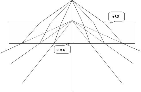
Figure 4 Â Schematic diagram of virtual light source
As shown in Fig. 4 , we regard the center of the sample cell as a light source, and the light emitted by the light source is refracted through the inner and outer surfaces of the sample cell, and transmitted according to the formula of the plane refraction image distance.

The physical meaning of a virtual light source is that the scattered light that we see from the sample cell appears to be from the point at the virtual source.
So how do you use a virtual light source?
In the experiment, we placed the forward virtual light source and the backward virtual light source on the central axis of the scattering device respectively. It is necessary to align the probe with the position of the virtual light source. This step is very important, which determines whether the scattering can be accurately detected. Information, if this step is missing, there will be a big difference between the direction of detection of scattered light and its actual direction of scattering.
Data processing results and analysis
We process the measured raw data, normalize the experimental results and then use Excel to get the following comparison chart:
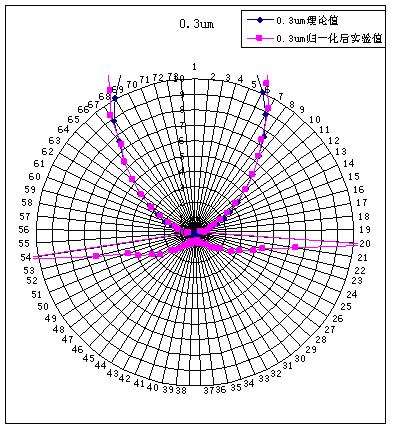
Figure 5  0.3μm experimental value and theoretical value comparison chart
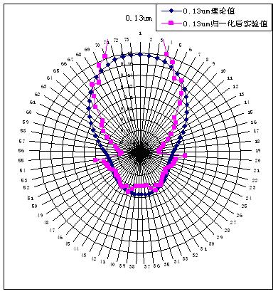
Figure 6  0.13μm experimental value and theoretical value comparison chart
From Figures 5 and 6, we can easily find that theoretically, the large particle backscattered light signal intensity is much smaller than the small particle backscattering, which means that the backscattered light signal is very important information for small particles. For 0.3μm particles, the forward scattered light signal agrees well with the theoretically calculated scatter signal, and the backscatter signal agrees poorly with the theory, which is compared with the reflected light pair we mentioned earlier. The effect of the results corresponds, because the large particle backscatter signal is relatively weak, and the effect of the reflected light is relatively obvious. For the scattering of 0.13μm particles , the experimental results are in good agreement with the theoretical results except for the range of 15° . The results of the forward scattering experiment are generally small. The main reason may be that the back surface of the sample cell is due to the laser. The back-measured scatter signal caused by the reflection of the light source is generally too large, so the forward measurement result is relatively generally small.
Through the above experimental research and analysis on submicron-sized particles, we need to improve several aspects of the experiment to design a better sub-micron particle size analyzer. For example, we can design the scattering device. More precise, the sample cell is fixed at the center platform angle, the horizontal direction can be fine-tuned; several suitable fiber angle probes are fixed around the center platform, and each probe is aligned with the virtual light source within its measurement range. Then, the fiber optic probes are simultaneously connected to a photomultiplier tube through a gating device, and the scattering information is displayed on the computer, and the signal is directly processed by the analysis software, and finally the result of the particle size corresponding to the signal is obtained. .
HbA1c And Blood Glucose Test Quality Control
A1Cchek Pro,A1Cchek Express,Hba1C Quality Control Reagent,Glycohemoglobin Quality Control
Wuxi BioHermes Bio & Medical Technology Co., Ltd. , https://www.biohermesglobal.com