In the higher automation chemical control system, the regulating valve is used as the terminal execution device of the automatic regulating system, and receives the control signal to realize the continuous adjustment of the chemical process. The failure occurring during the operation is directly related to the safe operation of the production device. According to the actual statistics of the site, about 70% of the faults originate from the regulating valve.
1 Overview
In an ammonia plant, a section of furnace is the core of the conversion section, and any interlocking action that causes a furnace to be shut down will result in the shutdown of its subsequent process system. The control of the negative pressure of one section of the furnace is the key. The air compressor gas turbine outlet burns exhaust gas, and part of it is used as a section of furnace combustion air. The oxygen content of the combustion air of a section of furnace is controlled by AV-03010 to ensure that the gas in the furnace is fully burned; the other part is to use the waste heat in the convection section of the furnace. The furnace negative pressure is controlled by PV-03048A/B; some is controlled by HV-02001 for venting. The air passages controlled by these valves are large, and the same multi-plate connecting rod pushing mechanism is adopted, which requires a large power, and the pneumatic actuator and the control gas path are complicated. For precise control, PV-03048 is controlled by A valve (small valve) and B valve (large valve), and one or two of them are required according to working conditions. These valves participate in the interlocking TRIP03.5 control to ensure safe operation of a section of the furnace system under normal negative pressure. When the gas turbine jumper or a section of the furnace pressure rises more than 100Pa, TRIP03.5 action: cut off a section of furnace combustion air AV-03010 and convection section exhaust gas discharge valve PV-03048A/B, and open the exhaust gas vent valve HV- 02001, and issued a jump signal to TRIPB. These valves repeatedly fail to control during driving or stroke verification, which jeopardizes the control of the furnace negative pressure.
2 There is a problem
The function of PV-03048A/B is to stably adjust the high temperature exhaust gas discharged from the gas turbine to the convection section of a furnace to assist in controlling the negative pressure of the furnace. In the overhaul, the PV-03048A/B valve does not operate when driving. The valve is a cylinder type regulating valve. The gas path is very complicated. The preliminary inspection found that the solenoid valve coil is not magnetic enough, resulting in a small output of the solenoid valve. The valve does not switch and the valve does not move. After replacing the solenoid valve, it still can't control the negative pressure of the furnace, and the negative pressure interlock switch will cause the jump to be caused by the chain. AV-03010 does not operate after overhaul. Check that the solenoid valve has electricity, the valve side is not open, the valve adjustment is out of order, and the furnace heating system cannot be opened normally.
3 Reason analysis
3.1 Introduction to Control
Taking PV-03048B valve control as an example, the original control gas circuit diagram is shown in Figure 1.
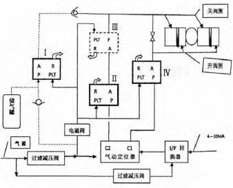
Figure 1 Original control gas path diagram
In the control chart, I, II, III, and IV are respectively four air control valves. PLT is the control port, R is the vent, and P and A are the vents. Among them, the air control valves II, III, IV are FC accident-off type, PLT has air-time air control valve P-A pass, PLT no gas when P-A is unreachable, A-R pass; air control valve I is FO accident open type When PLT has gas, P-A is not available, A-R is connected, and PLT is P-A when there is no gas.
During normal operation, the solenoid valve is charged and ventilated. The gas is connected to the PLT port of each pneumatic control valve through the solenoid valve and sent to the PLT end of the four pneumatic control valves. The valves II, III and IV are opened and the valve I is closed. The I/P converter accepts the main control 4~20mA signal, and outputs it to the pneumatic positioner after conversion. The two outputs C1 and C2, C1 pass the air control valve IV gas path to the valve opening side of the regulating valve cylinder; C2 through the air control valve II , III off the regulating valve gas path to the regulating valve cylinder closing valve side. The upper check valve ensures that the valve gas cannot be vented to the air control valve I. In this way, the main control 4 ~ 20mA signal is turned on and off to adjust the valve.
What needs to be emphasized is the line of the air control valve I. Its function is to forcibly close the regulating valve PV-03048B in the accident state of the solenoid valve losing power or losing the air source, so as to realize the accident closing function of the regulating valve. At this time, the valve I is opened. When there is a gas source, the gas source passes through the lower check valve, the valve I, the upper check valve, and the closed valve gas path to close the regulating valve; when there is no gas source, the gas stored in the gas tank is usually stored. Source, through the valve I, the upper check valve, the valve closing the gas circuit to close the regulating valve. The lower check valve ensures that the gas source in the gas tank is not lost. At the same time, the function of the air control valve III is to close the electromagnetic valve in the event of loss of power and the loss of the air source, and to ensure that the valve is not vented due to the accident, because the P and A ports of the air control valve III are reversed, PLT After the gas is lost, the P-A is closed, the A-R is turned on, and the P port is connected to the gas side of the accident closing valve, which ensures that the accidental closing valve gas cannot be emptied.
3.2 PV-03048B can not act reason analysis
(1) It is observed that the valve sometimes moves slowly. The inspection found that the valve cylinder has a gas string phenomenon, and the piston seal ring of the double cylinder was replaced, and sometimes it can be operated. Even if it can be operated, it is very difficult to start after the valve is fully closed.
(2) Since the valve is a multi-turn plate linkage mechanism, the start is not smooth, and it is suspected that the resistance of the valve operation is large. Check each coupling and bearing and find that these places have high resistance to dry movement due to the high operating temperature of the valve. Fill with high temperature grease and the manual switch is flexible.
(3) After stopping the car again, the valve does not move. The inspection found that no matter how many signals were given, there was always gas on the valve closing side and the valve was closed. Disconnect the positioner C2 side output, there is still gas on the valve side. It is suspected that the air control valve I fails to switch. After changing the valve I, the phenomenon remains the same, indicating that the valve I is not faulty.
(4) The analysis believes that the reason why the air control valve does not switch is that the control air pressure is insufficient. The reasons for the low control air pressure may be: 1 measuring the solenoid valve supply voltage, without load 20VDC, with load 14VDC, solenoid valve power 3W, the load capacity may be insufficient to make the solenoid valve not fully open; 2VP-41 pneumatic positioner is a gas-consuming positioner, in which the balanced spool valve cores that control the two outputs of C1 and C2 are long-term sliding wear, and the air leakage is increased. , the valve has been positioned inaccurately, the air consumption of the whole circuit must be increased, the control air pressure is reduced, the air control valve can not be switched; 3 once the PLC is stopped, the corresponding inspection or other reasons will be performed, and the solenoid valve of the valve will often be powered off. The air control valve is reset, and when the power is restored, the solenoid valve is insufficiently opened due to the above reasons, the positioner partial pressure is too large, the air control valve controls the air pressure low, and the air control valve cannot be switched.
4 Control gas path transformation
Taking PV-03048B as an example, the modified gas path control diagram is shown in Figure 2.
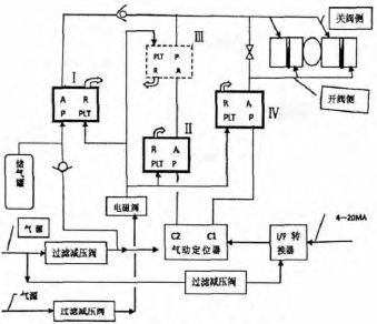
Figure 2 Modified air circuit control diagram
Comprehensive failure reasons, in addition to replacing the pneumatic positioner, regularly adding high temperature resistant grease to each coupling bearing, and introducing a gas source directly to the solenoid valve, and replacing the solenoid valve with large flux and low power consumption. The valve improves the control gas pressure. After testing, the four gas control valves can be switched normally, and the problem is solved satisfactorily.
5 Conclusion
Overhaul PV-03048B, PV-03048A, AV-03010 were controlled to control the gas path. After the transformation, the control gas path was switched and controlled normally, and the valve moved freely. After nearly one year of production and operation practice, these three valves work normally, and there has not been a failure so far. This kind of transformation is simple and easy, low cost and strong in practicability. It explores a new way for the troubleshooting of other control valves of the synthesizer.
Water Distiller Price,Automatic Water Distiller,Veterinary Water Distiller,Stainless Steel Water Distiller
ZHEJIANG FOMOS MEDICAL TECHNOLOGY CO.,LTD. , https://www.ifomos.com